NASA Mentorship
OVERVIEW
As a senior in the engineering strand at the Governor’s School for Science and Technology, I am required to complete a mentorship outside of school hours. I applied for, interviewed with, and was accepted into a mentorship with a NASA aerospace engineer, Dr. Nathaniel Blaesser, who performs conceptual design and analysis of advanced aircraft concepts. My work involves an open-source aircraft design platform called OpenVSP (Vehicle Sketch Pad). This software allows a user to quickly design, draft, and model configurations of different aircraft. In other words, this tool is basically CAD (Computer-Aided Design) specifically made for those in the aerospace industry. This software allows the geometry of an aircraft to be designed using parametrics; basing the model off of different features and constraints. The user is able to input the different components on an aircraft like the fuselage (main body of the plane) or wings and edit them in a highly visual and intuitive way. The different parts of the plane can then be modified through the definition of quantities like chord thickness, length, and aspect ratio. In addition to the efficiency, conceptual aircraft design enabled by OpenVSP, this program is also incredibly valuable as it translates the aircraft into models that can be run in engineering analysis programs to study things like the CFD, or computational fluid dynamics, of the aircraft (Lockney).
Although OpenVSP is an extremely useful tool, it does not have a customizable engine component that can be added by a user. If someone wanted to incorporate an engineer into their model, they would have to do it manually by making a stack (a feature that can be made by individually defining cross-sections) or designing the feature in another way. This research project is focused on modeling and coding a customizable turbofan that can be added to the model with one click. A turbofan engine is basically a mixture between a jet engine and a propeller. This means that some of the air flows through the core of the engine while the rest of it flows through a fan portion outside of the core (Turbofan 2020). In a turbofan engine, the pressure created in the jet portion of the engine is used to rotate a crankshaft that, in turn, spins the fan and creates more thrust. The customizable turbofan engine allows for a faster and more accurate model to be made. This addition to the software will improve the efficiency of the design process as a whole, and also allow people to focus more time and energy on different aspects of design, maybe even allowing for a more fuel-efficient or more aerodynamic model to be made.
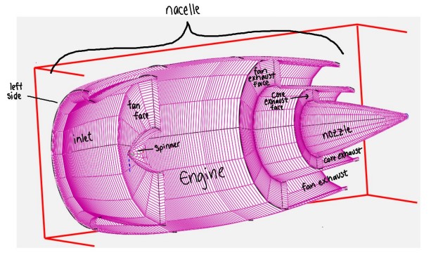
Any improvements that will cut out extra time in the VSP modeling process will be beneficial. In order to actually code and design a customizable turbofan component, a new VSP part will be made. VSP parts are coded individually, allowing the user to add different features such as the fuselage, wings, and hopefully engine, into the model. One of the biggest advantages of this feature is that it will give people the ability to focus on the critical aspects of the engine, while the code takes care of the rest in the background. The geometry section of the program, where the user can change the model, is divided into both a nacelle and engine tab. The nacelle (outer shell of the engine) tab allows the user to change features like the maximum diameter, length, and strength of the nacelle and inlet. Additionally, the engine portion contains sliders that adjust the area of the fan face, so that the bypass ratio (ratio of air that goes around the fan versus through the core) can be measured easily. The area of the core exhaust and fan exhaust in the back of the engine also work similarly to the fan face and can be adjusted using a slider. These features are all very beneficial, as in design, things like inlet strength ( the thickness of the front wall of the engine) have a very specific effect on the model and its aerodynamics. For example, there are certain values on the inlet that help optimize the airflow, making it essential for the customizable turbofan engine model to be easily iterated and tested. (Farokhi, 2020).
Overall, this research project will have a huge effect on the efficiency and design of aircraft. Hopefully, by the end of the school year this turbofan engine component will be added to OpenVSP as a new feature for use by engineers.
ENGINEERING JOURNAL DETAILS
9/28/20 - Introductory Work
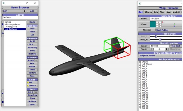
Up until this point in time working was mainly spent on an introduction and basic information that will be involved in the project. This involved getting familiarized with open-source software called OpenVSP and reading excerpts from several papers involving aeronautical design and aerodynamics. OpenVSP is the tool that is used by many aerospace engineers to design a framework for different planes and test how they would function with regard to things like lift and drag. The picture below is one of the planes that was made to practice using the software.
9/28/20 - Introductory Work (continued)
This meeting was also used to decide what exactly the research project was going to be focused on. In this project, a new adjustable component is going to be added to OpenVSP so that users can quickly insert an engine and change its dimensions. As of right now, there are several components like these available including things like wings and the fuselage. The plan is to determine what factors are important in sizing an engine, and ensure that those can be used to create a specific engine for each plane that is made in the software. Below is the dropdown list of all of the components that are available so far.
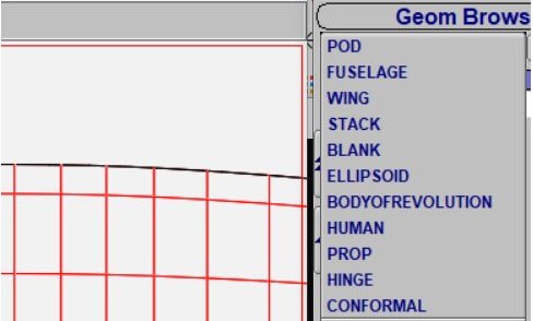
Afterward, it was decided that the next main step would be to learn how to model an engine using the stack feature above. This is a pretty simple task, however, it is difficult to figure out how to use all of the different features of the software.
10/5/20 - Basic Engine Design
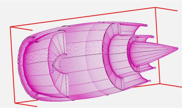
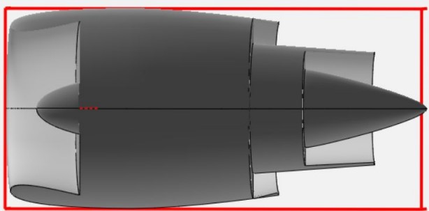
The next week was spent designing the framework for the engine and learning about the history and mechanics of engines in general. This specific engine that the research project will be involving is called a turbofan engine. This is basically a jet engine with a fan bypass where some of the air, instead of flowing into the core, can go around the outside of the core through a fan. This is a more fuel-efficient version of the jet engine and can be seen in a lot of commercial airlines. The drawing below depicts the turbofan engine that was drafted in OpenVSP.
10/12/20 - Parts of an Engine/Labeling

During this week, the different parts of an engine were further explored. This was necessary because in order to design a custom component it must be known what parts are important to an engine. These terms will be used in the future through advanced links and eventually as variables.
10/19/20 - Designing with Advanced Linking
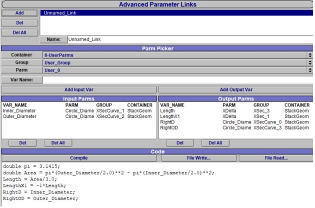
This week the beginning of the programming for the project was started. A hollow cylinder-like component was designed using the stack feature. A stack is a part that can be made cross section by cross section to create a certain component for the aircraft. Advanced linking allows the user to define certain parts of the cross section in relation to others so that if one thing is changed the other will change too.
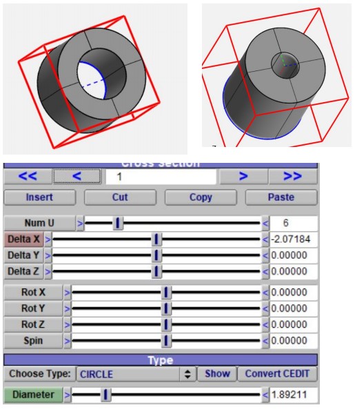
For this specific example, diameter and length were linked together. When the input (green) was made larger or smaller, the output (red) was changed also so that the part could be made into a thinner, wider cylinder, or a thicker, taller cylinder.
10/26/20 - Practice Programming of a VSP Part
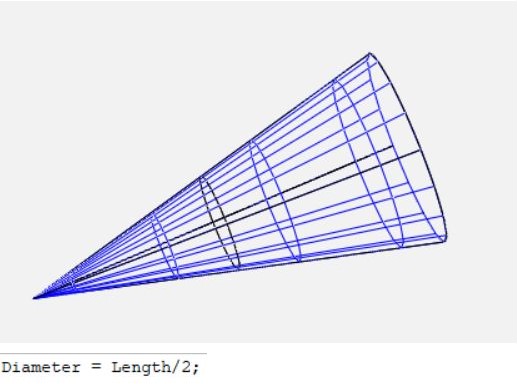
The same concept from the previous week was practiced with different examples (like the cone above). In order to be able to design an engine as a custom component, a VSP Part must be coded. This is similar to a stack, except all of the code is done in the background, and the cross sections would be defined beforehand so that the user is only able to see and alter certain parts of the component.
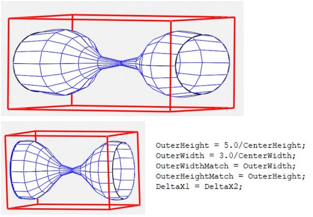
The above example was an hourglass-shaped example in which the width and height can be manipulated to either be stretched out vertically or horizontally, while the length can be changed to match the users preference. This is a useful activity to help gain experience with how code works and how variables are able to be changed in relation to one another.
11/2/20 - Front of Engine Draft
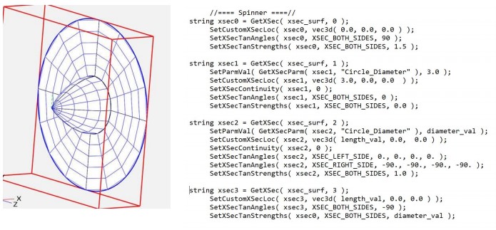
This week the front portion of the engine, including the spinner, fan face, and inlet was drafted as a VSP Part. In order to do this, four cross sections were added to the code (shown above). These included one point for the tip of the spinner and circles for the base of the spinner, the edge of the fan face, and the front of the engine itself. After this was done, it was decided that the user should be able to control the length of the spinner, the diameter of the spinner, and the area of the fan.
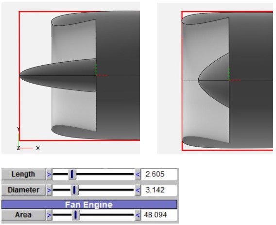
As mentioned before, for the spinner, both the diameter and the length were added into the Gui (the place that creates the sliders and labeling) so that the user could adjust their values (as shown above). Next, the area of the fan was made adjustable. This was done by declaring both the spinner diameter and fan diameter as variables so that the area could be calculated. A picture of the adjusted fan area is shown on the next page.
11/9/20 - Initial Design of Entire Engine
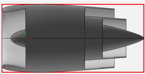
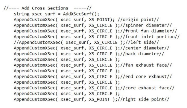
Above, the work from this week is shown. The entire engine was drafted using cross sections. Each of the cross sections were added, and their delta x (distance left or right) was imputed into the code. The diameter and entry and exit angles were also added. The entire portion of code that went into making the basic engine draft would be a lot to insert here, so the declared cross sections were added instead (shown on the following page). The cross sections were also labeled so that it was easier to know which part of the code correlates to which part of the engine. Additionally the labeling helps ensure that multiple people can understand the code, and that things can be changed a lot easier.
11/16/20 - Inlet Design with Variables
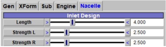
This week the first portion of the engine was customized so that the user could manipulate the length, and strength on the left and right of the front opening. Also notice that two tabs were defined, one for the engine (the inner part of the component), and one for the nacelle (the shell that surrounds the jet and fan portion). There is no picture of the engine inlet being manipulated right now, but it will probably be added later
11/23/20 - Nacelle Design with Variables
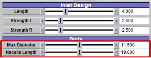
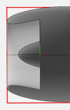
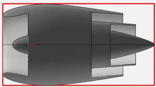
This week, two more sliders were added to the nacelle tab. These were max diameter and nacelle length. The max diameter allows the user to decide how big the widest part of the engine will be. This feature can be seen in the first picture below where it is slightly over-exaggerated. Next, the nacelle length was made a variable. This allows the user to control how long the portion of the engine from the front to the end of the nacelle is (this nacelle does not include any part of the core, it is the outermost shell). The change in nacelle length feature is exemplified in the second picture below.
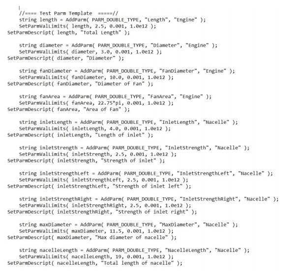
All of the defined variables in the code so far are shown below. These are what enables the user to customize the component.
Work Continued Through Spring Semester (then into the summer)
As this project continued, the engine GUI became more organized, and the engine itself had more features to customize. ll of the features for customization of the engine are sorted into just three tabs as pictured.
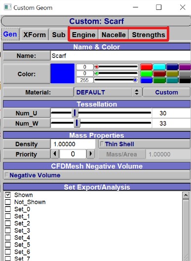
Using the Engine tab (which controls the internal surfaces of the model related to the engine itself), Nacelle tab( controlling the outer shaping of the engine), and the strengths tab (which gets into the nitty gritty shaping of the crosssections and inlet), the model is fully customizable. The amazing thing and the big advantage about this is that by using one of the special features of VSP, an image or design model of an engine can be entered into the background of the CAD program. Using this, a very accurate model can be created in seconds just by using the sliders to match the engine model to the background image (as shown below).
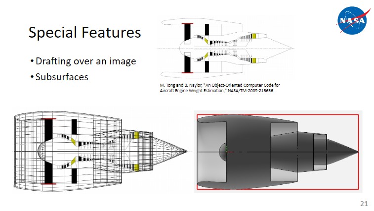
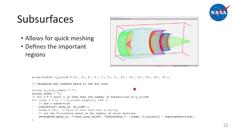
Another main feature was the addition of subsurfaces into the model. This allows for quick meshing when it comes to CFD and allows the user to easily identify and tell the computer which surfaces of the engine would be experiencing which kind of fluid motion. THis involved a little bit more complicated code but was well worth it for the ease that it provided the user.
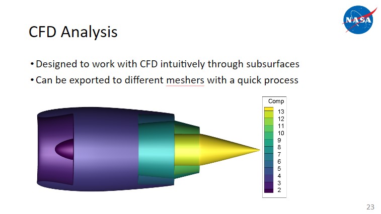
The end goal of this was to get this engine exported into CFD analyzers so that with the quick and easy addition of accurate turbofan engines to aircraft models, the CFD calculations and data would be significantly more accurate. This is especially important seeing as a lot of drag and complications in fluid motion occur near the engines as that is where many disturbances happen.
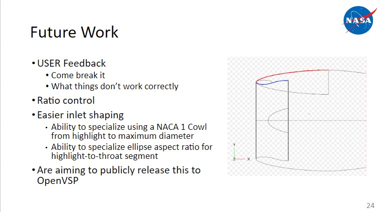
The future work of this involved focusing even more on the inlet - one of the most complicated aspects of the engine when it comes to aerodynamics and CFD. The ways that this was approached are shown below:
All of this work was presented at the 2021 OpenVSP Workshop and can be watched below: video